Lesson 5 : Ultrasonic sensor for measuring distance with Menya IoT kit
- WatchIT Group

- Dec 10, 2019
- 3 min read
Updated: Dec 21, 2019
What is Ultrasonic sensor
As the name indicates, ultrasonic sensors measure distance by using ultrasonic waves. The sensor head emits an ultrasonic wave and receives the wave reflected back from the target. Ultrasonic Sensors measure the distance to the target by measuring the time between the emission and reception.

figure 1 : Ultrasonic sensor HC-SR04.
Specifications Ultrasonic sensor HC-SR04
Provides 2-400cm non-contact measurements function
Operating Voltage 5v
working frequency 40KHz
Trigger input signal : 10uS TTL pulse

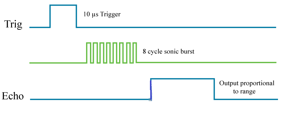
figure 2 : working principle of the ultrasonic sensor
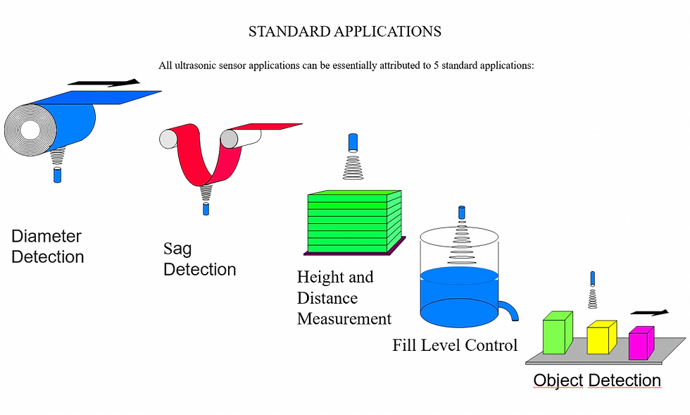
Application of Ultrasonic sensor
Ultrasonic sensor can measure the following parameters , without even getting in contact with the medium which is to be measured:

The HC-SR04 Ultrasonic Module
The HC-SR04 Ultrasonic Module has 4 pins, Ground, VCC, Trig and Echo. The Ground and the VCC pins of the module needs to be connected to the Ground and the 5 volts pins on the Arduino Board respectively and the trig and echo pins to any Digital I/O pin on the Arduino Board.

In order to generate the ultrasound you need to set the Trig on a High State for 10 µs. That will send out an 8 cycle sonic burst which will travel at the speed sound and it will be received in the Echo pin. The Echo pin will output the time in microseconds the sound wave traveled.

If the object is 10 cm away from the sensor, and the speed of the sound is 340 m/s or 0.034 cm/µs the sound wave will need to travel about 294 u seconds. But what you will get from the Echo pin will be double that number because the sound wave needs to travel forward and bounce backward. So in order to get the distance in cm we need to multiply the received travel time value from the echo pin by 0.034 and divide it by 2.

Circuit diagram

Sketch
How the code works
You create variables for the trigger and echo pin called Trigpin and Echopin , the TrigPin is connected to digital pin 9 while the Echopin is connected to pin 10.
You also create three variables of type long: duration. The duration variable saves the time between the emission and reception of the signal
In the setup(), initialize the serial port at a baud rate of 9600, and set the trigger pin as an output and the echo pin as an input.
In the loop(), trigger the sensor by sending a HIGH pulse of 10 microseconds. But, before that, give a short LOW pulse to ensure you’ll get a clean HIGH pulse
Then, you can read the signal from the sensor – a HIGH pulse whose duration is the time in microseconds from the sending of the signal to the reception of its echo to an object.
Finally, you just need to convert the duration to a distance using the formula above.
pulseIn();
Description
Reads a pulse (either HIGH or LOW) on a pin. For example, if value is HIGH, pulseIn() waits for the pin to go from LOW to HIGH, starts timing, then waits for the pin to go LOW and stops timing. Returns the length of the pulse in microseconds or gives up and returns 0 if no complete pulse was received within the timeout.
The timing of this function has been determined empirically and will probably show errors in longer pulses. Works on pulses from 10 microseconds to 3 minutes in length.
Syntax
pulseIn(pin, value)
We need to divide the traveltime by 2 because we have to take into account that the wave was sent, hit the object, and then returned back to the sensor.
Finally, we print the results in the Serial Monitor
Thank you! Feel free to ask any question in the comments section below!😉


it'S WORKS
Dear Igor , the sensor has a range from 2-400cm non-contact measurements function, that means when it is too close it is out of range and might display unwanted values
it worked but why the distance increase when the object is set in 0 distance(too close)
and it helped me to get an idea for a project ;)
it worked really well (^U^)!!!